Enhanced IEC 61131 Guide
*License Required for Enhanced IEC
Topic Menu
Note: Enhanced IEC (EIEC) is available for most of the XL, XL Prime and RCC series.
Enhanced IEC Overview
The following enhancements are available in Enhanced IEC mode:
-
Introduction of fully tag-based addressing
-
Support for 128kBytes of variable space - The current IEC system works by mapping allocated variables to the PLC %R
 Retentive 16-bit registers. space. At the time of development, the OCS was limited to 9999 %R's. The Enhanced IEC development will remove the link between variables and %R's and will simply allocate 128kBytes of variable storage – equivalent to 64000 %R registers.
 -
More powerful Debugging and Simulation features - Breakpoints, Tracepoints can be set in the IEC logic files. Step in, step out and step over are available for IEC code. In simulation mode user can run the IEC program locally on the PC to test and debug during the development phase.
-
Support for Online Logic Change - With the addition of online change in IEC the application running in the unit will never be interrupted, even when making updates. The logic running in the OCS can be modified without putting the unit to idle mode. This is ideal for programs which require long periods of start up or shut down so that logic changes can be made without waiting for the machine to start or stop so that logic can be downloaded.
-
Introduction of Exception Handling - Allows user to trap errors which previously was difficult to find and frequently cause technical support calls
-
Support for LREAL
These numbers use IEEE 754-1985 format to store numbers in following ranges.
32-bit single-precision floating point (REAL) – -3.40282E+38 to +3.40282E+38
64-bit double-precision floating point (LREAL) – -1.79769E+308 to +1.7976E+308
Floating Point refers to both REAL and LREAL data types., LINT and LWORD Datatypes - Enhanced IEC mode supports LREAL (64-bit floating-point number), LINT (64 Bit Signed Integer) and LWORD (64 Bit Unsigned Integer) data types. -
Support of Bitfield - User can give meaningful name to every bits of a particular program variable
-
Support of Enumerated Datatype - Added support to enumerated data types.
Return to the Top: Enhanced IEC 61131 Guide
Enhanced IEC Mode
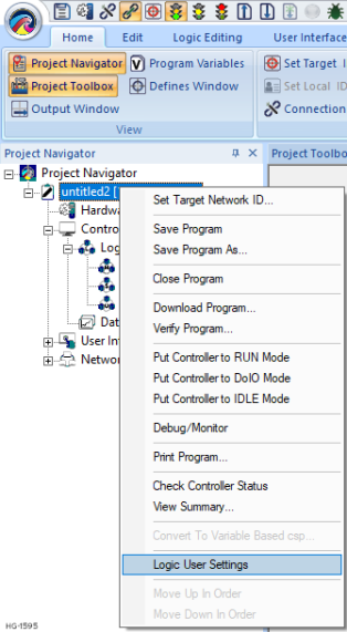
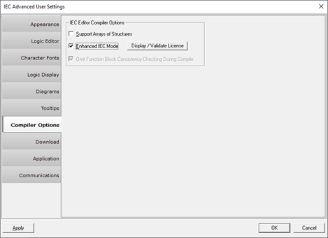
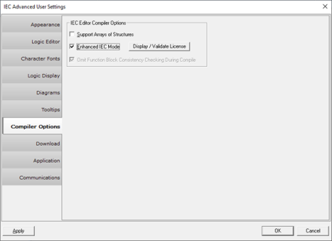
To enable Enhanced IEC mode, navigate to Tools > Editor options > Compiler Options and select Enhanced IEC Mode option. Users can also go to Project Navigator > Right click on Program > Logic User Settings > Compiler Options.
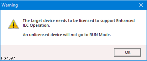
Selecting the Display/Validate License option displays the following warning message:
Selecting OK displays the following warning message:
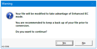
Click on Yes. Enhanced IEC mode will be enabled.
In order to make Enhanced IEC mode as default mode for any IEC applications, navigate to Project Navigator > Right click on Program > Logic User Settings > Application and select Enhanced IEC Default Enable option from Supported Program Types section.
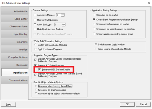
Click on Apply and then OK.
Return to the Top: Enhanced IEC 61131 Guide
Enhanced IEC Project Settings
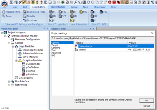
User can set Enhanced IEC project settings from Logic Settings > Project Settings option. Users can modify the settings according to the project requirement. See Online Change in EIEC* for more information.
Return to the Top: Enhanced IEC 61131 Guide
Enhanced IEC Settings and Data Types
Bitfields Window 
User can give meaningful names to every bit of a particular program variable. Go to Logic Editing > Bitfields, a window will appear where in user can insert Bitfield.
Example for Usage of a Bitfield
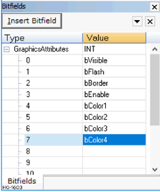
Step 1: Add a bitfield to match the attributes control format for graphical objects (user will need to be out of on line change and/or debug mode):
Step 2: Then create a variable of this type:
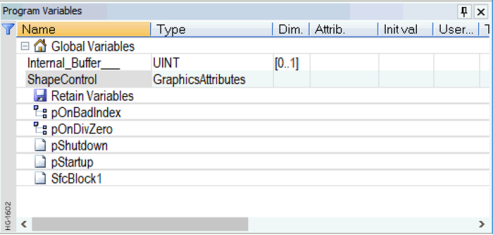
Step 3: Now in the graphics editor create a shape object with attributes controlled by this variable:
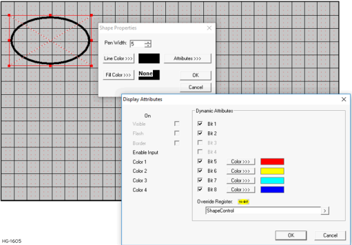
Step 4: Download to the OCS and enter debug mode and double click the value of ShapeControl to force the various bits and see the on screen shape change. For example here we set the visible, flash and color bits.
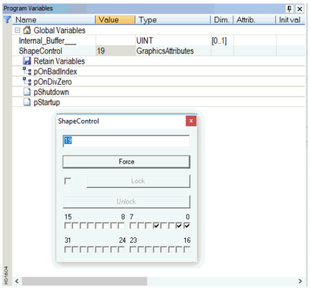
Note: Bits such as ShapeControl.bColor4 become valid BOOL![]() Boolean- [Data Type BOOL] - A single bit, binary value, or register/variable. Boolean points have only two possible values, 'TRUE' or 'FALSE'. variables, for example:
Boolean- [Data Type BOOL] - A single bit, binary value, or register/variable. Boolean points have only two possible values, 'TRUE' or 'FALSE'. variables, for example:
ShapeControl.bFlash := TRUE;
is a valid ST statement.
Enumerated Data Type 
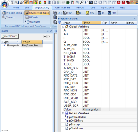
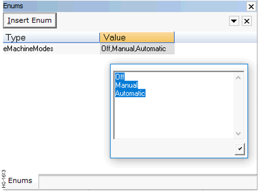
User can insert new Enum using "Insert Enum" button. Go to Logic Editing > Enumerated Types, a window will appear where in user can insert Enum.
Enum Example
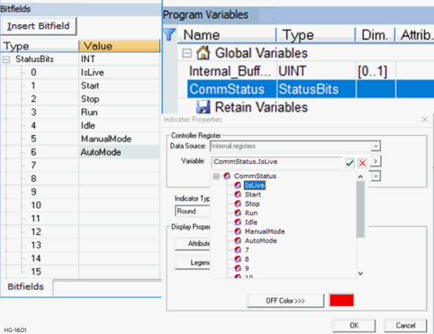
Step 1: Add a new enum eMachineModes with entries Off, Manual and Automatic.
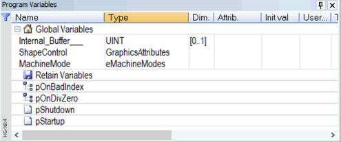
Step 2: Create a new Variable MachineMode of this type:
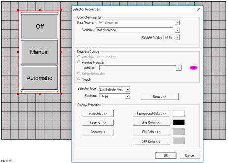
Step 3: Go to the Graphics Editor and create a new selector object.
Step 4: Download the Program to the OCS, and then start the debugger.
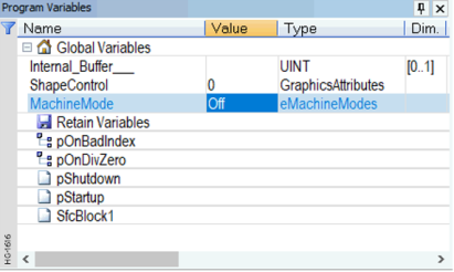
Observe How
-
Changing the ‘value’ of MachineMode in the debug window changes the selection in the graphics object.
-
Selecting a different item in the on-screen selector item changes the value in the program variables window.
Used in Logic
The values of “MachineMode” can be used in the control logic using (for example in ST):
MachineMode := Manual;
If MachineMode = Manual THEN
any operation code
END_IF;
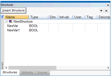
Structures 
User can insert new structure using Insert Structure button. Go to Tools > Structure Window, and a window will appear where in user can insert structure.
Return to the Top: Enhanced IEC 61131 Guide
Enhanced IEC Licensing
From Cscape 9.90 SP4 onwards, Enhanced IEC Licensing has been supported. To support the Enhanced IEC feature, the target device needs to be licensed. Without licensing, the device will not go to RUN mode.
With Enhanced IEC program opened, select Project Navigator > Right click on Program > Logic user Setting > Compiler Options, the following options will be displayed.
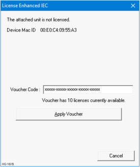
Selecting Display/Validate License displays the following window if the device is not licensed for enhanced IEC.
![]()
Selecting OK displays the following window.
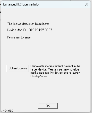
Select Obtain License and the following window will be displayed.
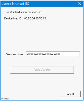
Applying valid voucher code displays the number of license currently available in the applied voucher code.
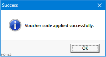
Select Apply Voucher. The following message will be displayed upon successfully applying voucher code:
Selecting on OK displays the following window:
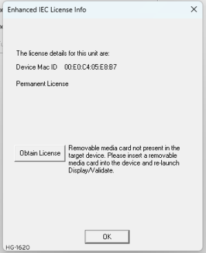
The device will be licensed for Enhanced IEC features.
Return to the Top: Enhanced IEC 61131 Guide
Exception Modules in EIEC 
NOTE: This feature requires Enhanced IEC License.
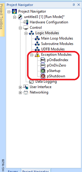
Exception Modules allows user to trap errors which previously was difficult to find and frequently cause technical support calls. Whenever user selects Enhanced IEC options the following four modules will get added automatically:


-
pOnBadIndex – This will be invoked if an array is handled with an invalid index, i.e., In the current IEC system an array out of bounds error can cause huge problems particularly writing out of bounds which may corrupt other variables or interfere with the operation of SFCs, causing the program to behave highly erratically. The new exception handler allows the errors to be detected and resolved.
-
pOnDivZero – This will be invoked if a divide by zero operation occurs, i.e., In the current IEC system a divide by zero causes a system exception which reboots the PLC whereas the new exception handler allows action to be taken in response, keeping the PLC running.
-
pStartUp – This will be invoked once when the PLC is starting up.
-
pShutdown – This will be invoked once when the PLC is shutting down.
Return to the Top: Enhanced IEC 61131 Guide
Program Migration in EIEC
Program Migration Overview
Most CSP files will load directly to the enhanced IEC system. Some modification will be required to deal with situations where multiple variables are mapped to the same registers. Some of the function blocks (listed below) have additional input/output parameters as they were previously having predefined associations with %R![]() Retentive 16-bit registers. and %T
Retentive 16-bit registers. and %T![]() Non-retentive single-bit registers..
Non-retentive single-bit registers..
|
Function Block |
Block in IEC |
Equivalent Block in EIEC |
|---|---|---|
| Serial Operation - Modbus |
Modbus Master |
Modbus Do Request/Old User Master |
| Modbus Slave | Modbus Map Slave | |
|
Modbus Slave with Exception |
Modbus Map Extended Slave |
|
| Networking – CsCAN | ||
| Put N Network Words | Net Put Word | |
| Get N Network Words | Net Get Word | |
| Put Network Words with Send command | Net Put Word Ex | |
| Screen | Display Screen | Force Screen |
Programming Restrictions - A couple of programming restrictions have been introduced to try to impose better programming practices on the user.
-
The user will no longer be able to give ‘aliases’ to I/O and system variables. Each variable must have a single reference by which it must be accessed.
-
There is no concept of %R
Retentive 16-bit registers.s, %M Retentive single-bit registers.s and %T Non-retentive single-bit registers.s, all variables are allocated in a common ‘data space’ so programs which previously imposed mapping to specific variables will have these mappings ignored. It is no longer possible to map a variable to, say, %R1001 because the register will no longer exists.
Below are some of the situations where modifications will be advised, if not indeed necessary.
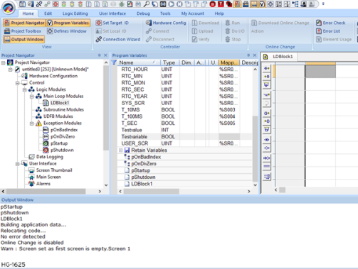
Situation #1: Variable Mapped to %R/%M/%T Register
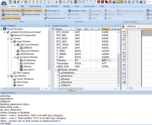
Necessary Action - None – the program will function as previously, but data will not be mapped to the required register.
Suggested Action - For clarity delete the tags
Situation #2. Multiple Registers of the same type accessing the same address
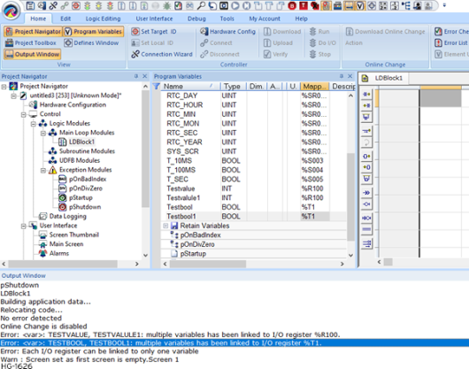
Here the same memory locations are being used as a single storage point then referenced by two different variables.
Necessary Action - Since the variables here will be separated and stored in separate slots in the common dataspace, the behavior of the program may change if no action is taken. There are a number of situations where user might see double use of the same register and each would require different resolution.
-
Programming Error - The register was double assigned by accident and luckily didn’t cause any problems, maybe the variable was just used for temporary workspace during calculations and was never actually used. In this case just remove the tags and the usage will be correctly separated.
-
To clarify the variable usage - A variable was given an ‘alias’ to improve readability in a different part of the code. For this come up with a better variable name which will work in both instances and replace all instances of both the original variable names with the new ‘all encompassing’ variable name.
Situation #3: Multiple Registers of different types accessing the same address
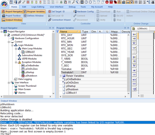
Possible reasons for this situation are the same as multiple registers of the same type accessing the same address, plus one other situation which users very often see:
Here there is a tendency to allocate a DWORD![]() DWORD - [Data Type DWORD] - A string of 32 consecutive bits. DWORD values are used where the value of the data is not as important as the bit patterns (shifts and rotates). for the status variable initially just to make the project compile. Later when access is required to the two registers individually an INT[2] is also mapped to the same register location to enable this.
DWORD - [Data Type DWORD] - A string of 32 consecutive bits. DWORD values are used where the value of the data is not as important as the bit patterns (shifts and rotates). for the status variable initially just to make the project compile. Later when access is required to the two registers individually an INT[2] is also mapped to the same register location to enable this.
Advice - Be accurate about variable type when creating variables to interface with status registers, I/O mappings, and other OCS standard features, and use a single mapping.
Return to the Top: Enhanced IEC 61131 Guide